Description
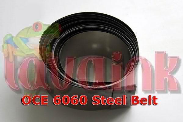
OCE Steel Belt 6060
Colorpainter 64S Steel Belt – U00101625600. This steel belt (64) is suitable for Seiko Colorpainter 64S and HP Designjet 9000 printers. This is the original Seiko part (number U00101625600). This belt is 468.5cm long and 2.5cm wide.
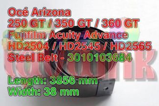
OCE Steel Belt Arizona-250-GT
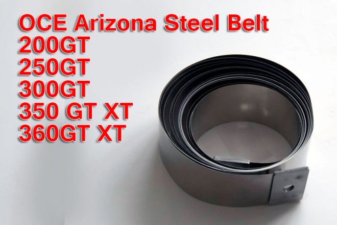
This generic Belt Gantry GT is suitable for Océ Arizona 250 GT printers. This is a high quality generic steel belt that corresponds to Océ part number 3010103684. This Belt Gantry GT is 385.6cm long and 3.8cm wide. Océ Arizona 250GT 350GT 350XT 360GT 360XT 200GT 300GT Fujifilm Acuity Advance HD2504 Acuity Advance HD2565 Acuity Advance HD2565 Acuity Advance HD2565 X2
OCE Steel Belt 6100
This belt is 2.5cm wide.
OCE Steel Belt Arizona-350-GT
This generic Belt Gantry GT is suitable for Océ Arizona 350 GT printers. This is a high quality generic steel belt that corresponds to Océ part number 3010103684. This Belt Gantry GT is 385.6cm long and 3.8cm wide. Océ Arizona 250GT 350GT 350XT 360GT 360XT 200GT 300GT Fujifilm Acuity Advance HD2504 Acuity Advance HD2565 Acuity Advance HD2565 Acuity Advance HD2565 X2
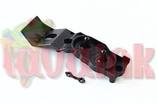
OCE Steel Belt Arizona-550-GT

OCE Steel Belt Océ Arizona 550 GT / Arizona 550 XT Fujifilm Acuity Advance HS HD3545 Acuity Advance HS HD3545 X2. This Belt-Drive Carriage is suitable for Océ Arizona 550 GT / XT printers. This is the original Océ part (number 3010108440). This Belt-Drive Carriage is 781.3cm long and 5.0cm wide.
OCE Belt
OCE Belt
How to Install OCE Belt
adjust two screws that controls the tension on left side of the printer, have someone push your carriage from left to right slowly while you turning the screws to see if the Belt is aligned. you can say that its aligned if its not riding up and down. 4.6.2. Replacing the steel Belt Caution :When replacing the steel Belt, be careful not to cut your hands by the Belt. Notes : Do not damage the steel Belt. Remove following covers before replacing the steel Belt.Side cover R: refer to “Removing side cover R” Side cover L: refer to “Removing side cover L” Front cover: refer to “Removing the front cover” Carriage cover: refer to “Removing the carriage cover” Y rail cover: refer to “Removing the Y rail cover” Unlock the head. Notes : Refer to “Head Lock Menu” Move the carriage from the capping position to the left. Rotate the 2 steel OCE Belt adjustment screws counterclockwisely to loosen the steel Belt. 1 = Steel Belt adjustment screws 2 = Steel Belt Remove the 2 screws fixing the steel Belt. 1 = Screws fixing the steel OCE Belt 2 = Steel Belt Replace the steel Belt.Notes : Be careful when handling the steel Belt. The steel Belt may be cut off when accreting dust to it or creasing it. Reinstall all parts in the opposite order of the removal procedure. Perform steel OCE Belt tension adjustment according to “Steel Belt tension adjustment”. Notes : Be careful when handling the steel Belt. The steel Belt may be cut off when accreting dust to it or creasing it. The driven pulley shaft is installed one way only. Refer to “Service Parts List/Exploded Views/Configuration Diagrams”, to install it correctly so that the bearing stoppers are on top. After installing the CR slave pulley assembly, move the carriage to the left and right manually to confirm that the steel Belt has been set equally in the center of the CR actuator pulley and the CR slave pulley assembly.
STEEL OCE Belt TENSION ADJUSTMENT The procedure for adjusting the steel Belt tension is explained below. This section explains the procedure for adjusting steel Belt tension. When removing/installing the steel Belt, adjust its tension. Tools required for work: The following tools are required when adjusting the tension of the steel Belt. Tension gauge: max. 2.0 N (200 g) Steel Belt tension attachment 2: for gauge diameter 2mm (0.08in.) or less Notes : Refer to “jig and Tool list”. Adjustment Procedure Use the following procedure to adjust the tension of the steel Belt. Place the tension gauge at the center of the steel Belt. 1 = steel OCE Belt 2 = Tension gauge. Notes : The regulation values for the tension of the steel OCE Belt are shown below. 1. 50 inch, 64 inch specifications: 1.0 N +- 0.1 N (100 g +- 10 g) 2. 87 inch specifications: 0.9 N +- 0.1 N (90 g +- 10 g) If the tension of the steel OCE Belt is not within the range of regulated values, adjust the steel Belt tension screws. 1 = Steel Belt 2 = Steel Belt tension screw 3 = CR slave pulley Move the CR cursor to the left and right once or twice. Adjust the CR driven pulley until the upper and lower margins are identical. Caution : If the tension is not equivalent across the entire OCE Belt, it could snap during operation. buy OCE steel belt www.LavaPrint.com